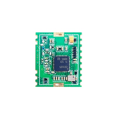
N511BS-B Information
N511BS-B-169M CC1125 Narrowband, +15 dBm, 160M - 175 MHz
N511BS-B-433M CC1125 Narrowband, +15 dBm, 410M - 480 MHz
N511BS-B-868M CC1125 Narrowband, +15 dBm, 860M - 960 MHz
CC1125 high quality fully functional protective transceiver module designed by 4-layer board. Sigfox, IoT, intelligent home, wireless meter reading, scientific research and medical treatment, and medium and long-distance wireless communication equipment.
N511BS-B leads all pins out of CC1125 for secondary development. All of the N511BS-B pin have exact ESD protect, each N511BS-B IO has additional ESD protection, and the antenna interface also has additional RF ESD protection. Rapid and Ardunio supports.
N511BS-B is suitable for free frequency band in EU and USA.
CC1125 Device Introduce
The CC1125 device is a fully integrated single-chip radio transceiver designed for high performance at very low-power and low-voltage operation in cost-effective wireless systems. All filters are integrated, thus removing the need for costly external SAW and IF filters. The device is mainly intended for the ISM (Industrial, Scientific, and Medical) and SRD (Short Range Device) frequency bands at 164–192 MHz, 274–320 MHz, 410–480 MHz, and 820–960 MHz.
The CC1125 device provides extensive hardware support for packet handling, data buffering, burst transmissions, clear channel assessment, link quality indication, and Wake-On-Radio. The main operating parameters of the CC1125 device can be controlled through an SPI interface. In a typical system, the CC1125 device will be used with a microcontroller and only a few external passive components.
ISM Frequency supported by N511BS module
169M band: 169 MHz to 170 MHz (China, EU)
433M band: 433 MHz to 435 MHz (China, EU)
470M band: 470 MHz to 480 MHz (China)
868M band: 868 MHz to 870 MHz (China, EU, USA)
888 MHz to 889 MHz (Australia)
915M band: 902 MHz to 928 MHz (USA)
RF rate of N511BS module
Narrowband FSK: 0 to 200 Kbps
APPLICATIONS
Sigfox network or point-to-point long distance transmission.
Narrowband system
Arduino device
Narrowband Ultra-Low-Power Wireless Systems
IEEE 802.15.4g Systems
With Channel Spacing Down to 12.5 kHz
Wireless Alarm and Security Systems
169-, 315-, 433-, 868-, 915-, 920-, 950-MHz
Industrial Monitoring and Control ISM/SRD Band
Wireless Healthcare Applications
Wireless Metering and Wireless Smart Grid (AMR and AMI)
Wireless Sensor Networks and Active RFID
Private Mobile Radios
Home and Building Automation
N511BS-B module
RF Interface | Parameter | Introduce |
Frequency | 169MHz, 433M, 868M, 915MHz | Support ISM |
Output Power | +15dBm | The maximum power 40mW |
Sensitivity | -123dBm | 1.2kbps |
Symbol Rate | 0.3-200kbps | Software programming control |
Frequency deviation | +/-1kHz | |
Working Volt | 1.8V -3.6V | 3.3V |
Emission Current | 20mA - 60mA | Typical 56mA |
Receiving Current | - | Typical 24mA |
Sleep current | - | Typical 0.1uA |
Antenna Interface | RF pin | - |
Communication Interface | SPI | Software programming |
Working Temperature | -40℃ -- + 80℃ | +25℃ |
Size | 19 x 16 x 3mm | - |
Package | SMD | - |
Distance | 2000m | In clear and open environment, the antenna gain is 3 dBi, the height above the ground is 2.5 meters, and the air speed is 1.2 kbps. |
N511BS-B Pin Function
Pin Number | Function | Description |
1 | RF | |
2 | GND | |
3 | GND | |
4 | GDIO3 | Connected to MCU IO port |
5 | RST | Connected to MCU IO port |
6 | VTC | Connected to MCU IO port, logic 0, close TCXO; logic 1, open TCXO. |
7 | GPIO2 | Connected to MCU IO port |
8 | MOSI | SPI |
9 | SCK | SPI |
10 | MISO | SPI |
11 | GPIO0 | Connected to MCU IO port |
12 | NSS | SPI |
13 | VCC | 1.8 - 3.6V |
14 | GND | GND |
N511BS-B Package
N511BS-B Pin Diagram
How to user N511BS-B TCXO
N511BS-B module startup sequence:
1) Power On TCXO;
2) Wait 2ms or more;
3) Reset module;
4) Configuration Register;
5) TX and RX.
N511BS-B module enter to sleepand wake on sequence:
1) Configuration Register;
2) enter cc112x/cc12xx sleepmode;
3) Wait 2ms or more;
4) Power Off TCXO;
5) Enter MCU power off.
6) Wait 2ms or more;
6) Power On TCXO;
7) Wait 2ms or more;
8) TX and RX.
TCXO power select:
1) Without sleep mode: VTC =VCC3.3V
2) sleep mode: VTC = GPIO(MCUGPIO control the power of TCXO)